Output device
This week was had to add an output device to a microcontroller board we have designed and program it to do something.
This week was had to add an output device to a microcontroller board we have designed and program it to do something.
The WallBot we had to make for our make a machine group assignments have a few of output devices such as two stepper motors and a servo motor. The stepper motor will control when the pen is going to touch the canvas and when it is just going to stay afloadt the canvas.
Thus I saw this as an opputunity to complete one part of our group project this week.
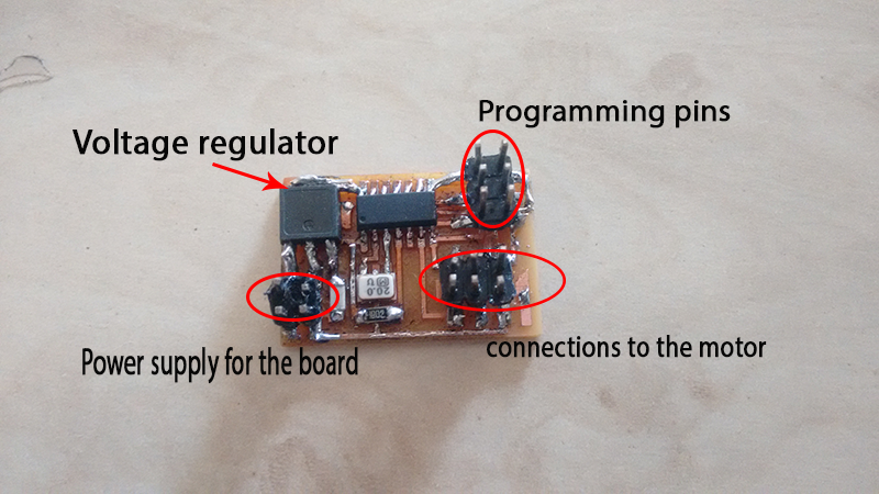
I tried to stick to the basics and decided to replicate Neil's servo board for this
After successfully running this board I will try out different ouput devices
I milled the board and populated it with the components, after soldering and trouble shooting the same I started to connect it with the programmer.
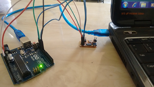
I am using Arduino Uno as an ISP to program my board.The connections are as follows
Miso- pin12
Mosi- pin11
Sck- pin 13
Reset- pin 10
Vcc and ground of the analog output of the arduino to the corresponding pins of the board.
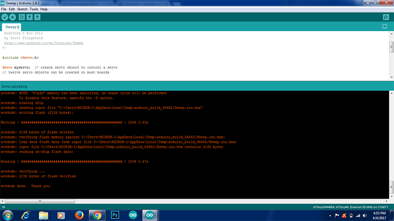
I used the sweep program in the examples of the arduino IDE to burn on the IC. After a few connections errors and rectifying them the program was uploaded on the IC
After it was the time to unplug it from the programmer and use it independently to drive the motors.
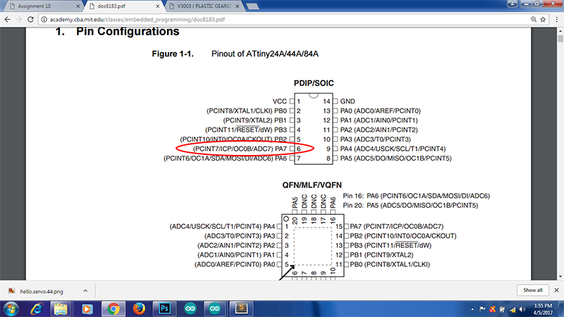
I am using Robokit's V3303 servo motor. I went through the datasheet of the same and figured out the connections and the operating voltage
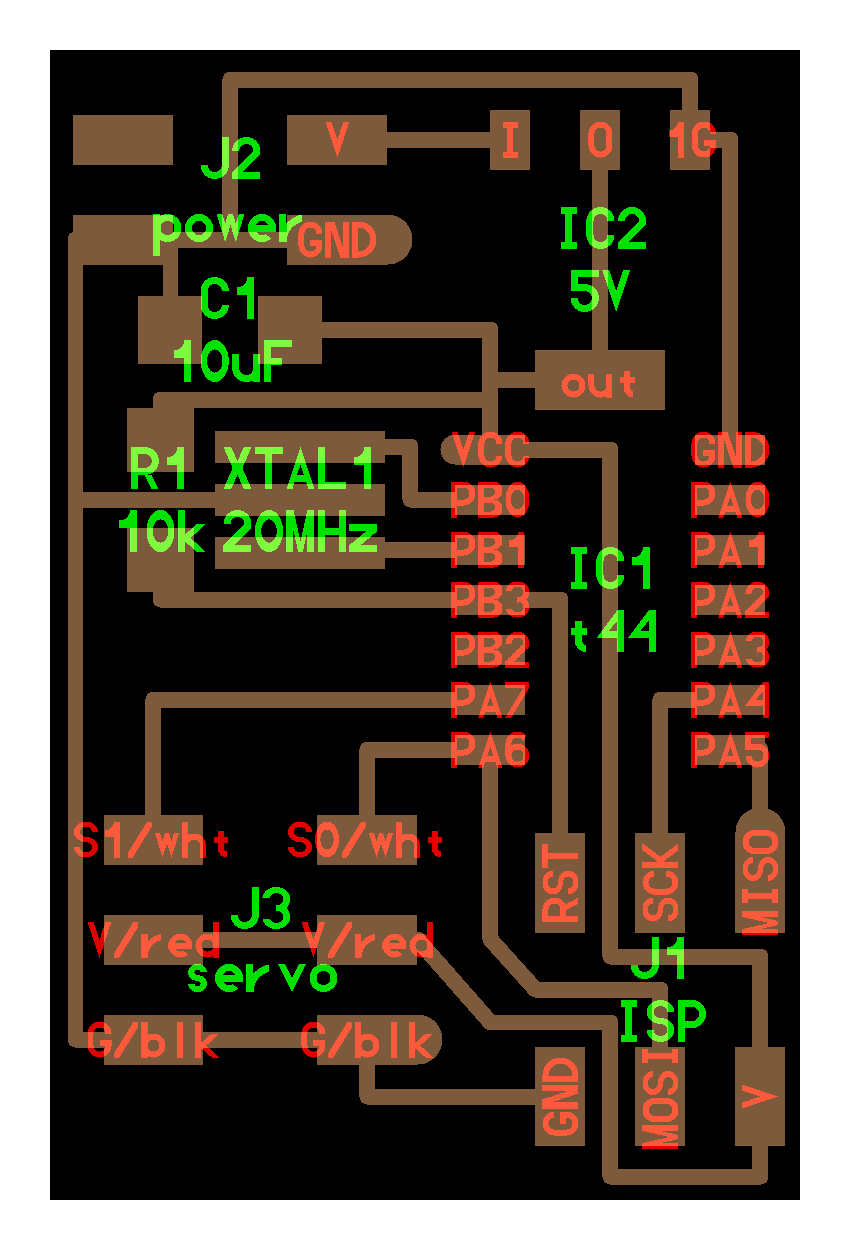
The motor has three terminals, a +ve terminal a-ve terminal and a signal terminal which is connected to the pin PA7 of the attiny 44
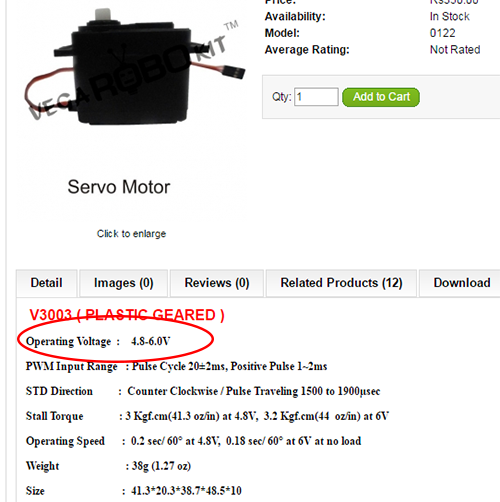
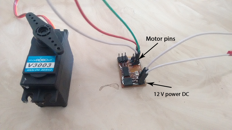
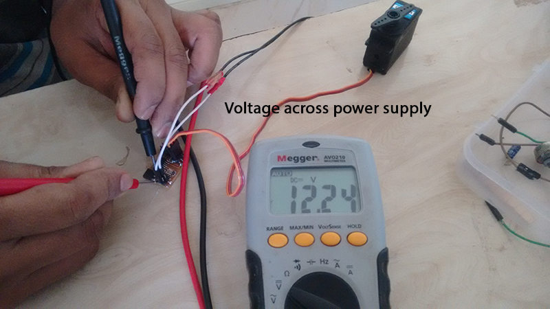
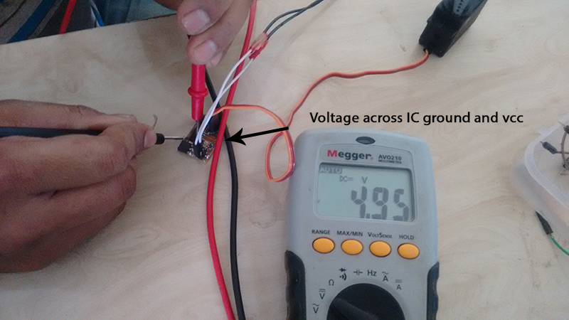
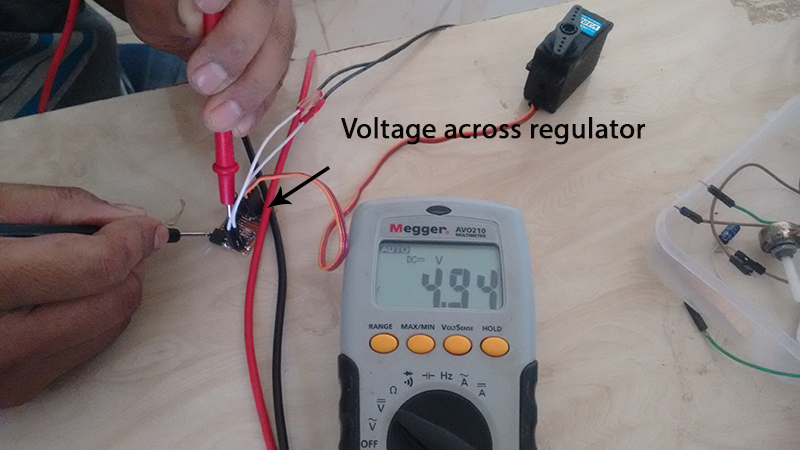
I used 12V 1 A adapter to power the board, but the motor works on 5V This is where the regulaor comes into play, it converts this 12V to 5V this voltage is enough to run the IC as well as the motor
I checked the input voltage and the output voltage at various points and found out that there was correct regulation of the voltage
Even after this check the motor failed to run
I double checked the connections and tried it again but it failed
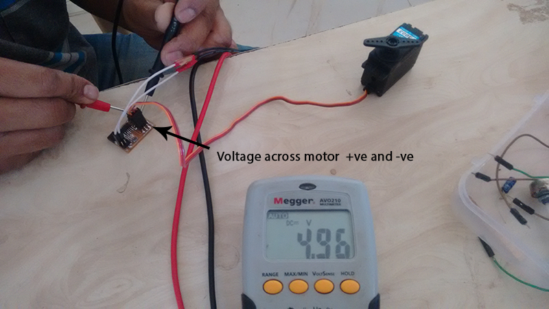
A strange thing happened though, the motor moves a bit when I connect the +ve pin of the motor on the board to a multimeter
I realised that by doing this I am connecting the +ve and the -ve pins of the motor on the board for a fraction of a second and that is when it gets powered and starts to move also, the motor has to move 180 degree clockwise and 180 degree anto clockwise. which is not the case here, it moves in one direction only
This means that the uploaded program is not performing its job. It is not behaving as I programmed itor there is an hardware issue
I will redesign the board and try it again
1 In this assignment I realised the importance of selection of the components, the voltage regulator we used regulated the 12V supply to 5V.
2 You should never do this
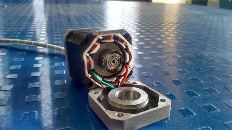
I wanted to see the inside of the motor, I opened a working stepper motor and when I tried to screw them back the motor did not perform the way it use to before, the motor moved with resistance
I searched on the net to find out that the gap between the stator and rotor coils of the motor are specially designed and maintan a specific gap which cannot be mainted by manual fixing.
I had permanently damaged the centering of the motor and thus rendered it useless
3 I had this errror while uploading the program on my IC,
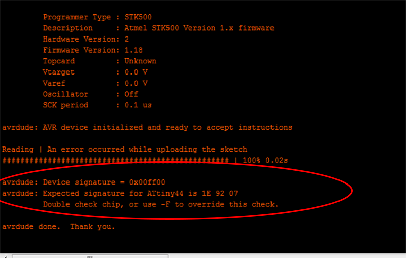
Again I searched on the net and found out that attaching a capacitor of 1-10 microfarad between the reset and the ground pins of the arduino prevents it for automatically resetting
I did the same, I used 7 microfarad but the problem still persisted.
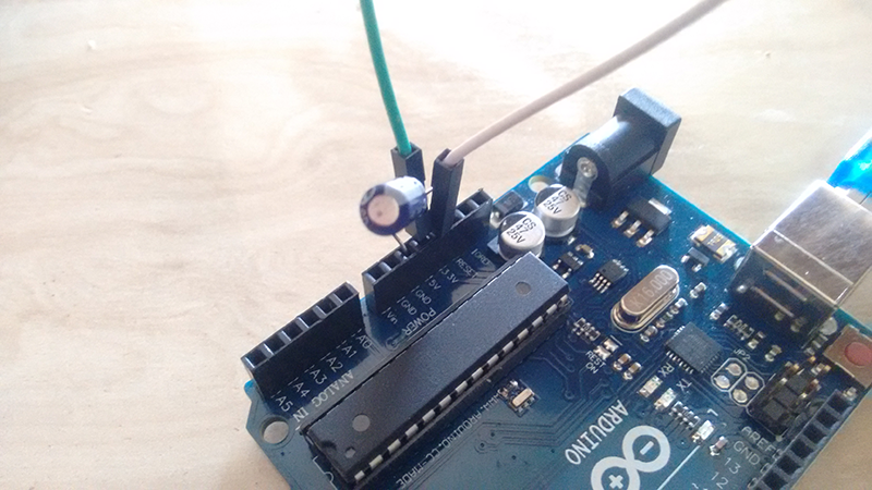
Then I used 10 microfarad in the same place and it worked, the program got uploaded
4 As Nadya said, Never, Never Never Hot plug in, this means that whenever we have to add a component to a cicuit we have to turn the power off or unplug it from the computer and do it.
I have wasted two arduino boards because I did not pay attention to this fact
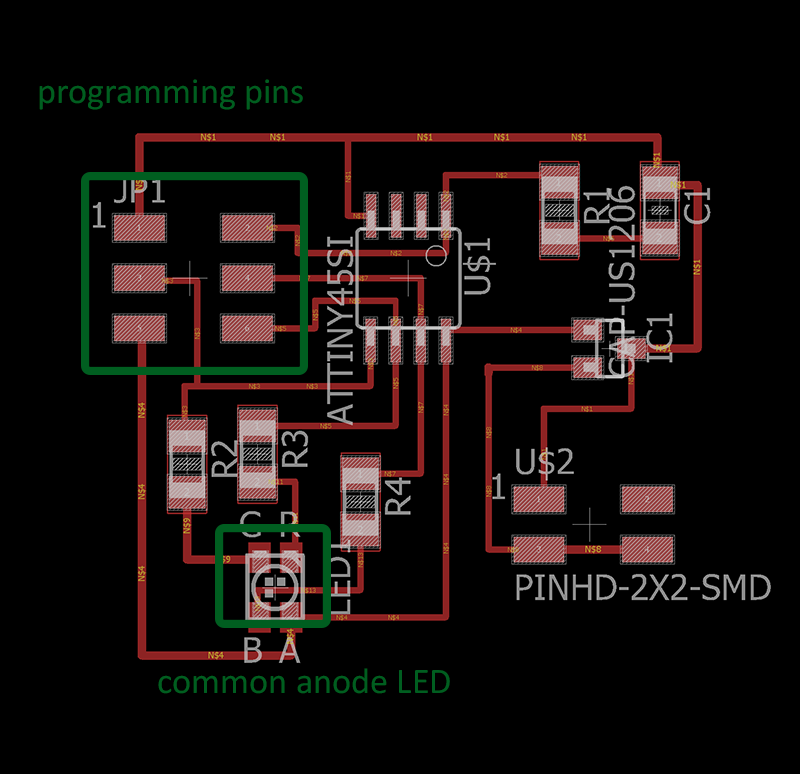
I had some time to go over the assignments once again, I made Neils, RGB board. Neil's board was very compact and thus I modified it a bit and made it a little less compact,I gave some spacing between the ISP header and the IC.
Pay attention to the connection of the RGB led, there are two types of RGB leds, one with common cathode and the other with common anode, Use the sonnections accordingly
Download the Eagle files from sch brd
Download the traces file and interior file
I downloaded the make and C file from the FabAcademy website and used my FabIsp as a Programmer. Download the files Make file and C file
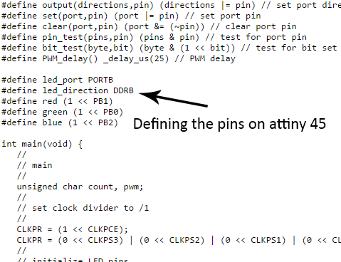
The code is basically defining the pins of the microcontroller and making them glow as per a fixed pattern

Here I used the instructions given in the embedded programming week, I used Avrdude to program my board, to know the steps I used here follow This
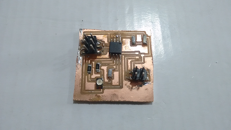
I have not cut the board because we were facing a few problems with the 1/32" endmill, we got it fixed eventually
Wow I can use this to change the lightings of the house according to my mood
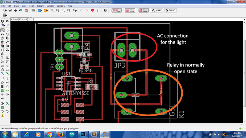
I am making a motion sensing light switch as a part of my final project for this I will be requiring a relay driving board that will be activate when a signal is received from the motion sensor and drive the light bulb on 230V AC supply
I completed this in the input devices week, so the details are included in that week but as it is having relay as an output device I will also include this here.
I designed the board in Eagle,Download the sch and brd files
The basic relay circuit looks something like this
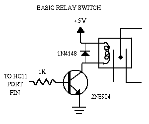
There are a few changes I made in the circuit, I used BC 848 as a transitor and IN4007 as a diode for the circuit, also I relpaced the 1K resistor with 49.9k resistor, as we trouble shoot one will oserve that the the resistor is not required sometimes.
Here the relay drives the light bulb, the relay gives a click sound when it switches this is when you know that the relay is working in a proper way
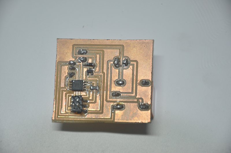
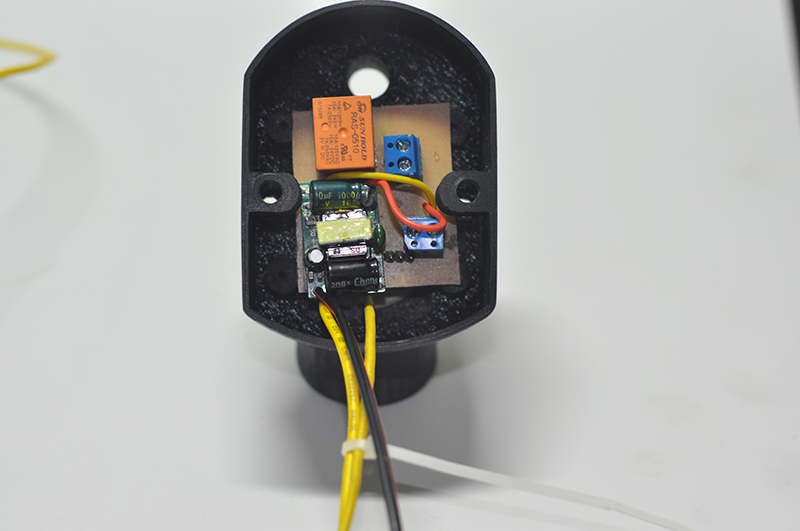
The relay and the connectors are soldered to the lower part of the board, this is to accomodate the bulky parts on the board.
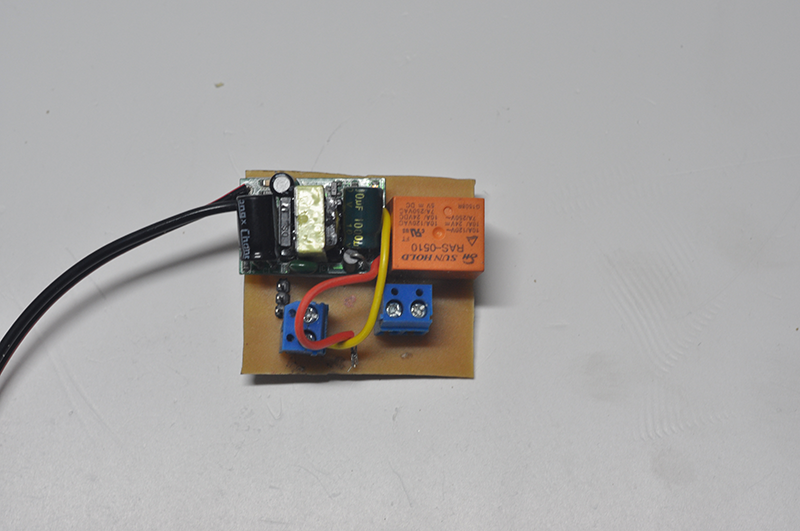
I had to take care that all the components they are nicely packed inside the enclosure that I designed during the 3d printing week.
The detailed working of the input output board will be explained in the Input devices week